DC Motor Control with Microcontroller ATmega8535

  • Sabtu, 31 Juli 2010
  • Posted by Learn Electronic

At mega 8535 microcontroller can use control dc motor that is on pin d where there have PWM control. DC motor can rotate because of the induction when the motor is connected to the DC voltage source. DC motor control with microcontroller if it is done more easily than without the microcontroller. We can change the direction of rotation of DC motor directly by changing the polarity of the voltage source. To change the speed of DC motors can be done by changing the size of a fox-voltage source. Control with a microcontroller as well as principled, but with an automated system. We do not have to change the cable from the motor to the battery if you want to change the direction of rotation, we just provide the logic 0 or 1 to the microcontroller is performed on the program in the microcontroller. To change the velocity is also easier because we simply use the existing PWM feature on the microcontroller. Maybe there are still many who do not know what PWM

PWM (Pulse Width Modulation) is a technique to get the effect of the analog signal from a digital signal to falter. PWM can be generated using only digital i / o which functioned as an output.


 In the example above the waves, the comparison between high signal (1) and low signal (0th) is the same. Above the wave is said to have 50% duty cycle. Duty cycle is the ratio between the width of high signal (1) the overall width of the cycle (cycle). If the PWM wave amplitude is 5 volts, then the average stress (as if to analog) that we get is 2.5 volts. Here's an example of wave PWM with duty cycle 10%, if the amplitude of wave 5 volts then we will get the average analog voltage 0.5 volts.


In  ATMEGA8535 have two way control PWM, the PWM can be generated from the first port input / output is enabled as output. The second is to utilize the facilities of the function of the PWM timer / counter which has been provided. With this facility, the timing of the process of high / low digital signal will not disrupt the sequence of other programs being executed by the processor. In addition, by using this facility to enter how many servings we lived on and off time period on a wave PWM registers. OCR1A, OCR1B and OCR2 is register a place set PWM duty cycle.
 
The following schematic DC Motor Control with Microcontroller ATmega8535 of my own, please trace itself, or if you want to please make my request in the comments section below ini. Click image to enlarge......


I separate the circuit into three main sections so that it is easy to understand and analyze our series, namely the minimum system, motor drivers, and motors (as a major expense). The minimum system the same as in my previous posting, the next part of the driver. in fact we can directly connect the microcontroller to the motor without a driver, this can be done if the motor that we use a small motor. we need a big motor for the drivers, these drivers can be made also with the MOSFET (often called the H-Bridge), we can use a more practical ie L298 driver ic, ni ijenis drivers able to control two motorcycles and also features the legs to control the PWM .
For our experiment we only use a single dc motor alone, here are photos from the series that I created.


For the program you can see below. Use the AVR Studio software (after AVR studio also install WinAVR is installed so that it AVRstudio supports the C language, because the standard AVRstudio using assembly language). To download your program can use the USB downloader downloader atapun series which has also been my post. The following program


#include <avr/io.h>
#include <util/delay.h>
#include <avr/interrupt.h>

#define    DDR_motor    DDRD    //DDR untuk Motor
#define    PORT_motor    PORTD    //PORT untuk Motor

#define en_ka         5        // Enable L298 untuk motor kanan
#define dirA_ka     2        // Direction A untuk motor kanan
#define dirB_ka     3        // Direction B untuk motor kanan
#define pwm_kanan    OCR1A

void delay_ms(int ms)
{for (int i=0;i<ms;i++){_delay_ms(1);}}

void maju(unsigned int pwm)
{
PORT_motor |=(1<<dirA_ka);        //motor maju
PORT_motor &=~(1<<dirB_ka);
pwm_kanan=pwm;                    //pwm motor kanan
}

void mundur(unsigned int pwm)
{
PORT_motor |=(1<<dirB_ka);        //motor maju
PORT_motor &=~(1<<dirA_ka);
pwm_kanan=pwm;                    //pwm motor kanan
}


int main (void)
{

DDR_motor=0xFF;
PORT_motor=0x00;


    TCCR1A= (1<<WGM11)|(1<<WGM10)|
            (1<<COM1A1)|(0<<COM1A0)|
            (1<<COM1B1)|(0<<COM1B0);
           
    TCCR1B= (0<<WGM13)|(1<<WGM12)|
            (0<<CS12)|(0<<CS11)|(1<<CS10);
    TCNT1=0x0000;
    OCR1A=0;
    OCR1B=0;
    sei( );


while(1)
{
mundur(1000);
delay_ms(5000);
maju(700);
delay_ms(3000);

}
}

see the main program, with a PWM motor will resign in 1000 over 5000ms (5 seconds) and then will forward denan PWM motor 700 for 3000ms (3 seconds). and the program will be repeated a maximum of motor-ulang.Kecepatan happen if we gave in 1000 and the minimum PWM value (motor stopped) if the PWM value of 0, see the main program, which is backward (1000) that mean the motor will spin backwards at top speed because the PWM is 1000
READ MORE - DC Motor Control with Microcontroller ATmega8535

PonyProg, serial device programmer

  • Selasa, 20 Juli 2010
  • Posted by Learn Electronic

If you are looking for a simple but powerful programmer you are right, it's here.
PonyProg is a serial device programmer software with a user friendly GUI framework available for Windows95/98/ME/NT/2000/XP and Intel Linux. Its purpose is reading and writing every serial device. At the moment it supports I²C Bus, Microwire, SPI eeprom, the Atmel AVR and Microchip PIC micro.
SI-Prog is the programmer hardware interface for PonyProg.
With PonyProg and SI-Prog you can program Wafercard for SAT, eeprom within GSM, TV or CAR-RADIO. Furthermore it can be used as a low cost starter kit for PIC and AVR. 

PonyProg works also with other simple hardware interfaces like AVR ISP (STK200/300), JDM/Ludipipo, EasyI2C and DT-006 AVR (by Dontronics).

0diggsdigg
PonyProg is a great software for flash memory programming. It supports a great variety of microcontrollers and other devices. Before using it you should check if your device is supported on the Official PonyProg 2000 Homepage. PonyProg 2000 is constantly updated and new devices are added.
The latest version is available on the Download Page.


So After you download and install it, you have to configure it for your hardware.
Go to   >> "Setup" >> "Interface Setup" 


Click on “Serial” if you are using AVR Serial port Flash programmer or “Parallel” if you are using AVR Parallel port Flash programmer. Next select “SI Prog I/O” (in case of serial) or “AVR ISP I/O” (in case of parallel).
Now click on “Probe” to check if your hardware is connected and working. If it says “Test Passed” it means your hardware is working with the configuration. If it says “Test Failed”, it means there is a fault in above configuration or your hardware.
Now click “OK”.
Then go to     >> “Setup” >> ”Calibration”. Click “Yes” on the next message box and wait for the “Calibration OK” confirmation.


Now Select “AVR micro” from the list of devices and select your AVR device from the next drop box.


Now load your hex file from the “Open Program Flash Memory File” button (1).

Then program the microcontroller by pressing the “Write Program Memory” button (2).

The Fuse bits of AVR microcontroller can be read and set by pressing the button with the lock (3).


Update: Its not always a good idea to use the latest version of PonyProg. I once updated from an older version and it started giving me "test failed" errors. So I went back to the older version and began working again. Latest versions are sometimes buggy so you should wait a while before updating.

If anybody wants any help with this stuff, just drop a comment or "Contact me". I'll be happy to help.
READ MORE - PonyProg, serial device programmer

Programming LCD AVR ATmega8535

  • Posted by Learn Electronic

This is an example programming C for interfacing microcontroler to LCD at AVR ATmega8535

#include
// Alphanumeric LCD Module functions
#asm
.equ_lcd_port=0x15 ;PORTC
#endasm
#include
//Declare your global variables here
Void main(void)
{
//Declare your local variables here
// Input/Output Ports initialization
// Port A initialization
// Func7=On Func6=In Func5=In Func4=In Func3=In Func2=In Func1=In Func0=In
// State7=T State6=T State5=T State4=T State3=T State2=T State1=T State0=T
PORTA=0x00;
DDRA=0x00;
// Port B initialization
// Func7=On Func6=In Func5=In Func4=In Func3=In Func2=In Func1=In Func0=In
// State7=T State6=T State5=T State4=T State3=T State2=T State1=T State0=T
PORTB=0x00;
DDRB=0x00;
// Port C initialization
// Func7=On Func6=In Func5=In Func4=In Func3=In Func2=In Func1=In Func0=In
// State7=T State6=T State5=T State4=T State3=T State2=T State1=T State0=T
PORTC=0x00;
DDRC=0x00;
// Port D initialization
// Func7=On Func6=In Func5=In Func4=In Func3=In Func2=In Func1=In Func0=In
// State7=T State6=T State5=T State4=T State3=T State2=T State1=T State0=T
PORTD=0x00;
DDRD=0x00;
// Timer/Counter 0 Initialization
// Clock source: System Clock
// Clock value: Timer 0 Stopped
// Mode: Normal top=FFh
// OC0 output: Disconnected
TCCR0=0x00;
TCNT0=0x00;
OCR0=0x00;
// Timer/Counter 1 Initialization
// Clock source: System Clock
// Clock value: Timer 1 Stopped
// Mode: Normal top=FFFFh
// OC1A output: Discon.
// OC1B output: Discon.
// Noise Canceler: Off
// Input Capture on Falling Edge
// Timer 1 Overflow Interrupt: Off
// Input Capture Interrupt: Off
// Compare A Match Interrupt: Off
// Compare B Match Interrupt: Off
TCCR1A=0x00;
TCCR1B=0x00;
TCNT1H=0x00;
TCNT1L=0x00;
ICR1H=0x00;
ICR1L=0x00;
OCR1AH=0x00;
OCR1AL=0x00;
OCR1BH=0x00;
OCR1BL=0x00;
// Timer/Counter 2 Initialization
// Clock source: System Clock
// Clock value: Timer 2 Stopped
// Mode: Normal top=FFh
// OC2 output: Disconnected
ASSR=0x00;
TCCR2=0x00;
TCNT2=0x00;
OCR2=0x00;
// External Interrupt(s) initialization
// INT0: Off
// INT1: Off
// INT2: Off
MCUCR=0x00;
MCUCSR=0x00;
// Analog Comparator initialization
// Analog Comparator: Off
// Analog Comparator Input Capture by Timer/Counter 1: Off
ACSR=0x80;
SFIOR=0x00;
LCD module initialization
lcd_init(16); //initialization LCD
lcd_gotoxy(0,0); //locate position in 0,0
//columns 0, lines 0
lcd_puts(“Hallo…”); //display string Hallo…
lcd_gotoxy(0,1); //locate position
//columns 0, lines 1
lcd_putsf(“My name is Rico”); //display string
while (1)
{
// Place your code here
};
}
READ MORE - Programming LCD AVR ATmega8535

USB Downloader for AVR microcontroler (ATMega 8535,16,32)

  • Posted by Learn Electronic

 For programming the AVR microcontrollers, Atmel has provided special software that can be downloaded from the Atmel website. Software is AVRStudio. This software uses assembly language as the language of instrumentality. AVRStudio addition, there are some third party software that can be used to create programs on the AVR. These third-party software using high level programming language like C, Java, or Basic. To make removal from the computer into a chip, can be used several ways such as using JTAG cable or using artificial Atmel STK.

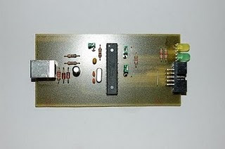
However, you also can use the schematic circuit above to make a downloader ATMega microcontrollers based USB ports. Here is my USB downloader which I successfully created. Imade the USB ASP Downloader based ATMega8. hopefully can help you.


READ MORE - USB Downloader for AVR microcontroler (ATMega 8535,16,32)

AVR Setup Programming your chip

  • Posted by Learn Electronic

What is a program?
When code is compiled into a windows program, its turned into "binary" which means its not human-readable (which is tough for machines to understand), instead it is machine-readable. Under windows, these programs (often called applications or executables) are often named ending with .exe (for example notepad.exe or winword.exe), on Macs, they are often named ending with .App (although the Finder hides it).
For microcontrollers, binary files end in .hex (short for Intel Hex Format) There are other formats possible, but this is pretty much standard.
Your compiler will generate a .hex file from code, and then all you have to do is transfer that .hex program to the chip!
What is flash?
As discussed in What is it?, the AVR chip has a small amount of flash memory in it. That memory is where the program is stored. When the chip starts up (you give it power) it starts running whatever program is in the flash. So all we have to do is figure out how to write to that flash
A good way to think about flash is to examine it as you probably are familiar with it. Flash storage is also used in MMC/SD cards, which are commonly used in MP3 players or digital cameras. If you look at the bottom of a card, you'll see little gold fingers. These are the interface pads.

If you look up in the MMC card specification, you'll find out that these are what the 7 pins are for. (SD/high speed cards may have extra pads, but that standard was added later because the existing standard was considered too slow for big megapixel cameras)
Pin # Pin Name Pin Function
1 #CS Chip Select (Activate)
2 SI Serial In
3 GND Ground
4 VCC Power
5 SCK
Data Clock
6 Not connected Not connected
7
SO
Serial Out
The power and ground pins are used to connect power to the chip. The Chip Select pin is used to tell the chip that it should wake up, Serial In pin is used to send data to the card, Serial Out is how data is sent from the card and Data Clock is how we tell the card how fast we want data to be stored or retrieved. Data is pushed in an out of the chip one bit at a time, so if the clock rate is 100KHz that means that 100,000 bits are transferred per second.
When you want to retreive or store data on a flash card all you have to do is stick the card into a flash card reader. The reader then has a driver on your computer which lets you simply drag files onto a picture on your screen and it does all the hard work of sending the data to the card.
OK, so what does this have to do with a programmer? Well, the microcontroller is like the flash card and the card reader is like the programmer. When you stick the chip into the programmer (or, more likely, the programmer cable into the circuit board that contains the chips) it allows the software on your computer to talk to the chip through the programmer. Usually you can just give a simple command like 'send this program over' and the programmer will do all the hard work of programming and verifying the data
In-System Programming interface
Every AVR has a set of pins that are the programming pins, you just have to connect the programmer to those pins in the right order and presto you are ready to program it. Unfortunately, nearly every chip has a different pinout so its imperative that you look in the datasheet for the correct pins.
For example, I'm a big fan of the ATtiny2313 chip, so lets open up the 'summary' datasheet (its only a dozen pages long instead of the standard 250. The first page has all sorts of information about what is in the chip.
Quick Quiz : How much EEPROM does the chip have? How about flash storage? RAM?
The second page has pinouts. We will be dealing with the PDIP package (Plastic Dual In-line Package) which is the kind that looks like this:
The pinout is reproduced here
The chip has 20 pins. Look carefully and you'll notice 6 of these pins are equivalent to the SD/MMC card pins. There is a power pin (VCC) and a ground pin (GND), there is also an SCK pin (its called UCSK for some reason) a Serial Out pin (MISO - Master In Serial Out ) and a Serial In pin (MOSI - Master Out Serial In). The only thing is doesnt have is a /ChipSelect pin. Instead it has a /RESET pin, which acts in a similar way. When the /RESET pin is at a postive voltage (the same voltage as VCC) the chip runs the program, when the /RESET pin is at ground (the same voltage as GND) then the chip stops and listens for programming instructions on the programming pins.
All SD cards have the same fingers in the same place so that when you slide it into the card reader, the right pads are connected. AVR programming works in a similar way. Instead of pads, the chip is often placed in a circuit board which has header pins that the progammer plugs into, the header pinout is standardized so that any programmer can be used once the header is wired up correctly.
There are two standards for AVR in-system programming:
The left is the 6-pin header standard, the right is the 10 pin standard, the headers look like this:
Here is an example photo showing what it looks like when the chip is wired up with a 6-pin header
The black mark on the PCB and header indicate pin #1. You can trace the wires to correllate the pins of the chip to the pins of the header and verify for your self that this breadboard is correct.
READ MORE - AVR Setup Programming your chip

Robot info

  • Posted by Learn Electronic

FIRST Robotics began in 1989 as a way of encouraging students to choose careers in math, science and technology, while also building their life skills and instilling a spirit of "gracious professionalism" and humility in its participants. Without "chest thumping" or "sticky-sweet platitudes," as the site explains, young people engage in competitions where they build robots.

The Junior FIRST LEGO league is for 6-9 year olds. The FIRST LEGO league targets younger children ages 9-14, while the FIRST Robotics Competition helps high school age students. The FIRST Tech Challenge provides more affordable robotics technology to high school students. More than 137,000 kids participated in last year's program, spanning across 42 countries from Germany and the UK to Turkey and Israel.FIRST Robotics founder Dean Kamen is an inventor, physicist, engineer and entrepreneur. He is perhaps best known for inventing the Segway Human Transporter, an environmentally friendly short distance travel solution. He's also developed the HomeChoice portable dialysis machine (Baxter Healthcare) and the Independence IBOT 4000 mobile robot system (Johnson & Johnson).

He's currently working on a water purification system that promises to provide clean drinking water to 1.1 billion people around the world. For his efforts, he's received the Heinz Award in Technology, the National Medal of Technology presented by President Clinton (2000) and the Lemelson-MIT Prize (2002), among others.

For 2009, the FIRST Robotics Competition will be called "Lunacy" to celebrate the 40th anniversary of our moon landing and will be held in Atlanta April 16-18. This year's autonomous robots will be restricted by size and weight (no more than 5 ft tall, no wider than 38 inches, no deeper than 28 inches and no heavier than 150 lbs) and must be able to pick up orbit balls (2-point moon rocks, empty cells and 15-point super cells) and transfer them into a trailer hitched to their opponent's robot in just two minutes and fifteen seconds.

While 80-90% of the teams participating this year will be returning from previous years, there are 300 rookie teams joining as well. Of course, even given the charitable contributions, each team will likely need to come up with $9,000 - $10,000 to cover meals, transportation, lodging, food, robot parts and lab fees.


The Baby Boomers grew up fascinated by the Space Race and the emergence of heroic astronauts as role models. Today's youth are more into computers. Even so, television shows like "Mythbusters," "Build It Bigger" and battling robot competitions are trying to intrigue young people to look to physics, engineering and technology. 
READ MORE - Robot info

Robot In Our Life

  • Posted by Learn Electronic

What is a robot?
 There’s no precise definition, but by general agreement a robot is a programmable machine that imitates the actions or appearance of an intelligent creature–usually a human. To qualify as a robot, a machine has to be able to do two things: 1) get information from its surroundings, and 2) do something physical–such as move or manipulate objects.

The word robot comes from the Czech word robota, meaning drudgery or slave-like labor. It was first used to describe fabricated workers in a fictional 1920s play by Czech author Karel Capek called Rossum’s Universal Robots. In the story, a scientist invents robots to help people by performing simple, repetitive tasks. However, once the robots are used to fight wars, they turn on their human owners and take over the world.

If you think robots are mainly the stuff of space movies, think again. Right now, all over the world, robots are on the move. They’re painting cars at Ford plants, assembling Milano cookies for Pepperidge Farms, walking into live volcanoes, driving trains in Paris, and defusing bombs in Northern Ireland. As they grow tougher, nimbler, and smarter, today’s robots are doing more and more things we can’t –or don’t want to–do.
Robots have been with us for less than 50 years, but the idea of inanimate creations to do our bidding is much, much older. The ancient Greek poet Homer described maidens of gold, metallic helpers for the Hephaistos, the Greek god of the forge. The golems of medieval Jewish legend were robot-like servants made of clay, brought to life by a spoken charm. Leonardo da Vinci drew plans for a mechanical man in 1495.
But real robots wouldn’t become possible until the 1950’s and 60’s, with the invention of transistors and integrated circuits. Compact, reliable electronics and a growing computer industry added brains to the brawn of already existing machines. In 1959, researchers demonstrated the possibility of robotic manufacturing when they unveiled a computer-controlled milling machine. Its first product: ashtrays.

Public fascination with robotics peaked in the early 1980’s, spurred in part by movies like Star Wars, which featured robots C3-PO and R2-D2 as helpful sidekicks to the their human masters. But interest sagged in a few short years as people discovered that getting robots to do things that we think of as easy–like moving across a cluttered room–is surprisingly difficult.
Today, robots are enjoying a resurgence. As computer processors are getting faster and cheaper, robots can afford to get smarter. Meanwhile, researchers are working on ways to help robots move and "think" more efficiently. Although most robots in use today are designed for specific tasks, the goal is to someday make universal robots, robots that are flexible enough to do just about anything a human does–and more.

Just name a boring or dangerous job; somewhere, a robot is probably doing it.  As mechanical workers, robots are ideal for jobs requiring repetitive, precise movements. Human workers need a comfortable working environment, salaries, coffee breaks, sleep, and vacations. Robots don’t. Human workers get bored doing the same thing over and over, boredom that leads to fatigue and costly mistakes. Robots don’t get bored.
Ninety percent of robots work in factories, and more than half are at work making automobiles. Car factories are so highly automated that most of the human workers are there mainly to supervise or maintain the robots and other machines. Robots assemble car body panels and weld them together, finish and paint the car bodies, and stack and move partially completed cars. 

Another example of a factory job done by robots is arranging chocolates in boxed assortments. Guided by a computer vision system, a robotic arm can locate a piece of chocolate on a moving conveyer belt, gently pick it up and turn it to the proper orientation, then deposit it in a specific location within a box on another moving conveyer belt. Sure, it’s a task that almost anyone could do. . .but could you do it 20,000 times over the course of an eight-hour shift?

 Robots are being put to a wider variety of manufacturing uses each day. In the computer industry, robots solder tiny wires to semiconductor chips. "Pick and place" robots insert integrated circuits onto printed circuit boards; these are used in all kinds of electronics, from radios to microwaves. Robots are also at work making and packaging drugs, textiles, and foods.
Certain dangerous jobs are best done by robots. Bomb disposal is one of these. Guided remotely using video cameras, robots like the Mini-Andros can be sent to investigate–and defuse–possible bombs. (See sidebar.)
Robots also venture into dangerously polluted environments, such as chemical spills and radioactive "hot zones" in nuclear power plants. Robug III is a spider-like robot specially designed to explore areas where extreme radiation would quickly kill a human. The need for a robot like Robug III was made clear during the Chernobyl accident in 1986. An explosion and fire ripped apart a nuclear reactor and released dangerous radioactive material into the air, making rescue and containment work nearly impossible.


READ MORE - Robot In Our Life